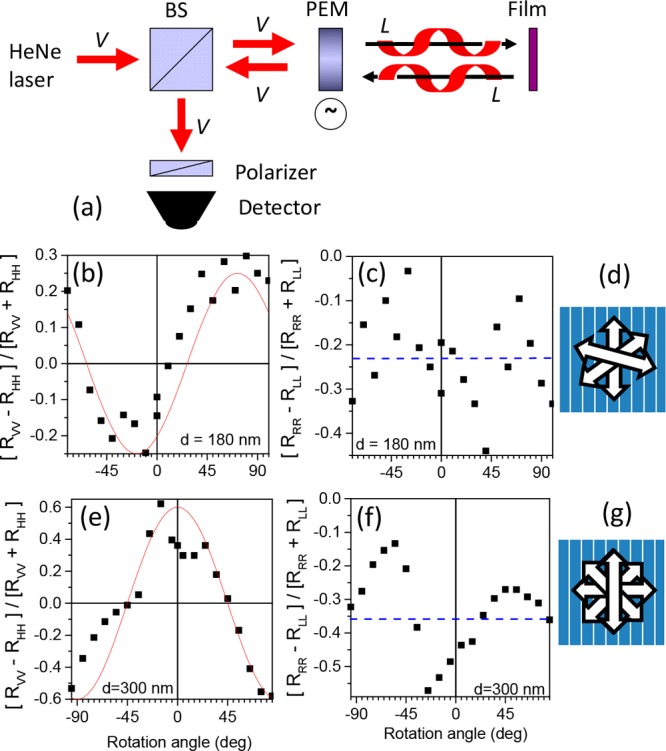
Figure 3.

(a) Schematic of the experimental set up for measurement of reflection from a film under normal incidence with selection of both the incoming and reflected polarization. V vertically linear polarized light, BS beam splitter, PEM photoelastic modulator. The case of the modulator at quarter wavelength retardation is shown with left circularly polarized incident light reflected as left circular polarized light by the cholesteric film. (b) Degree of linear polarization in reflection for vertically polarized (V) incident light into V reflected light and horizontally polarized (H) incident light into H reflected light for an aligned film of 1 with thickness d = 180 nm as a function of the rotation angle of the film around the surface normal. Zero rotation refers to the rubbing direction being vertical. Positive rotation refers to turning the polymer film in the clockwise direction as seen from the light source facing the polymer on top of the rubbed substrate. Wavelength of light: 543 nm. Red curve eq 7 with d = 300 nm and pitch = 600 nm, c) degree of circular polarization for right circularly polarized (R) incident light into R reflected light and left circularly polarized (L) incident light into L reflected light. Dashed blue line shows the average degree of circular polarization (c) schematic of the director in the 180 nm thick cholesteric film with a pitch of 600 nm. (e,f, and g) Similar for a 300 nm thick film of 1.
