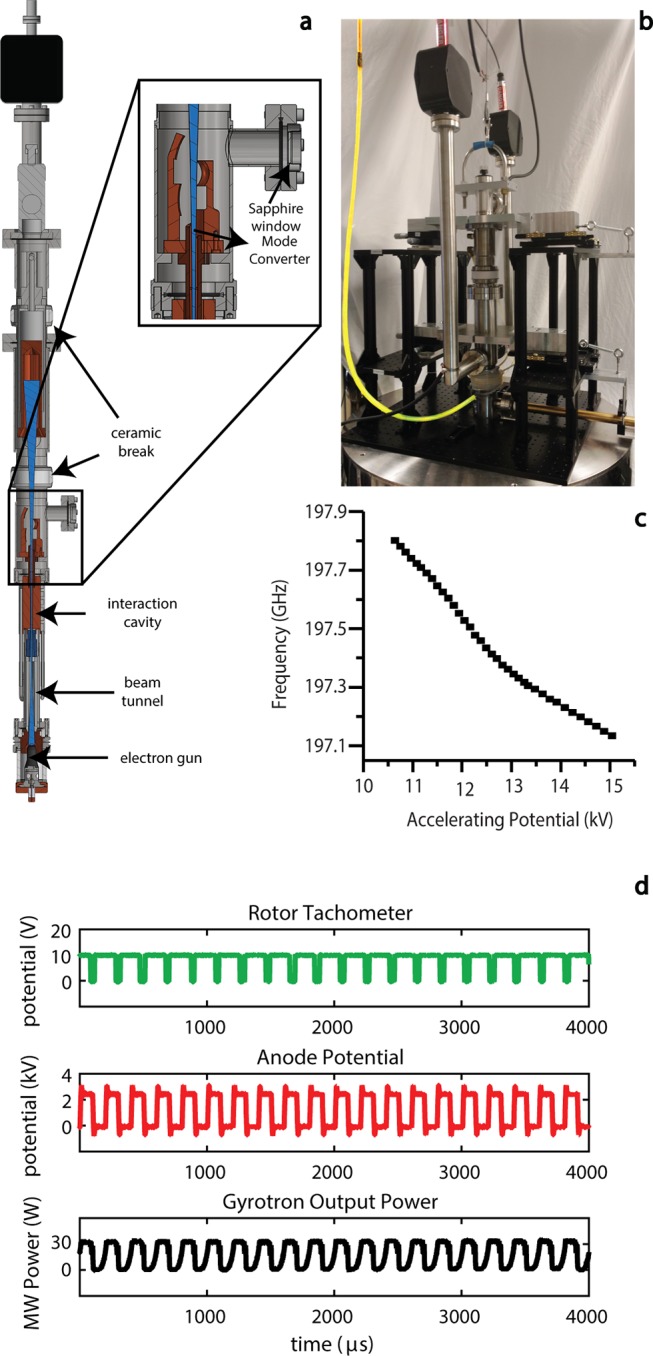
Figure 5.

(a) Computer-aided design (CAD) drawing of a 198 GHz gyrotron. (b) The gyrotron is connected by the wire (highlighted in yellow) to a low-capacitance amplifier. (c) Dependence of the gyrotron output frequency on the applied accelerating voltage. (d) Rotor-synchronized microwave power output from the gyrotron. The rotor tachometer reading is shown in green, the gating voltage pulses in red, and the microwave power modulation in black. Figure reproduced with modifications by permission of the Journal of Magnetic Resonance.53
