Figure 6.

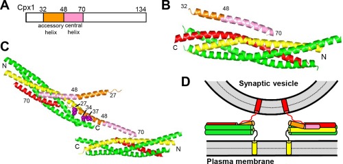
Structure and function of complexins. (A) Domain diagram of Cpx1. Numbers above the diagram indicate the domain boundaries and the length of the protein. (B) Ribbon diagram showing the three‐dimensional structure of the Cpx1(26–83)/SNARE complex145 (PDB accession code 1KIL). (C) Ribbon diagram illustrating the three‐dimensional structure of the complex between Cpx1(26–83) bearing the superclamp mutation and a SNARE complex that was truncated at the synaptobrevin C‐terminus160 (PDB accession code 3RK3). Two copies of Cpx1(26–83) and of the truncated SNARE complex are displayed to show how one Cpx1(26–83) molecule binds to one SNARE complex through the central helix and to another SNARE complex through the mutated accessory helix, resulting in a zigzag array. The three mutated residues (shown as brown spheres) are hydrophobic and bind to the hydrophobic groove left by the synaptobrevin truncation, but these three residues are charged in WT Cpx1. In (B,C), N and C indicate the N‐ and C‐termini of the SNARE complex, and selected residue numbers of Cpx1 are indicated. (D) Model illustrating how, upon binding of Cpx1 to SNARE complexes partially assembled between two membranes, the accessory helix would hinder closer membrane‐membrane proximity due to steric and/or electrostatic hindrance with the vesicle. For simplicity, only the SNARE motifs, TM regions and linkers between them are shown. In panels (B–D), Cpx1(26–83) is color coded as in panel (A), syntaxin‐1 is yellow, synaptobrevin red and SNAP‐25 green.
