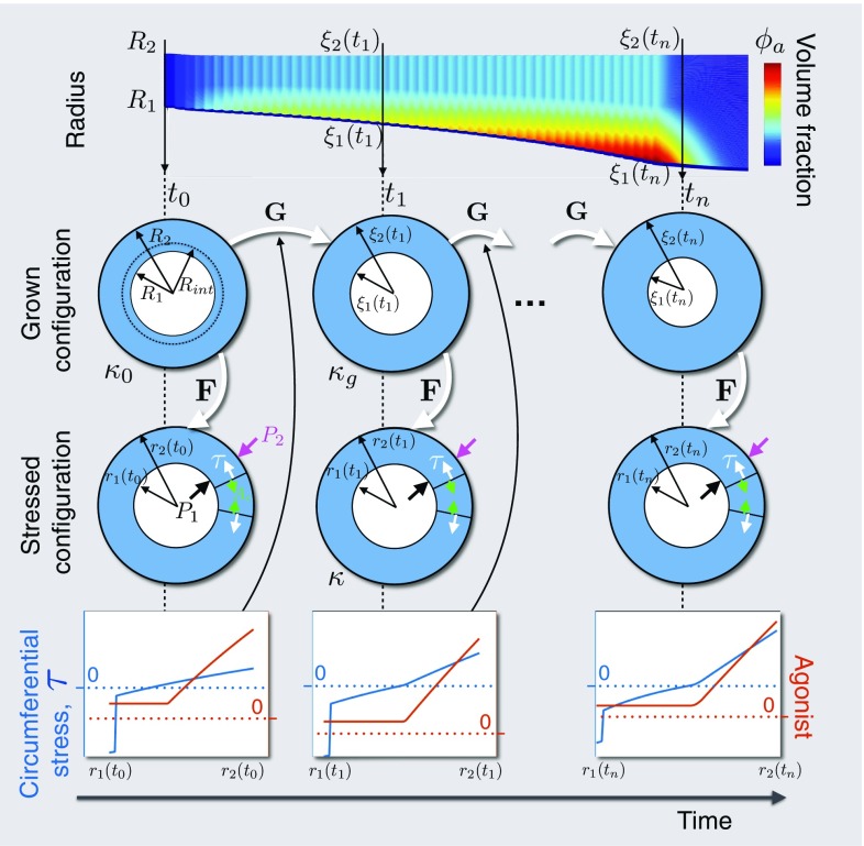
Fig. 1.
Configurations during finite growth of the airway wall. Top row: Schematic of the evolution of the airway wall geometry with time, with the colours correspoding to tissue constituent volume fraction. Middle rows: Schematics of the airway geometry in the grown and stressed configurations, at the indicated time. At initial time , the airway wall is defined by inner radius , interface radius , and outer radius in , the original, stress-free reference configuration. Airway wall growth is described by the mapping, , from the original configuration to , the grown, zero-stress configuration, defined by grown radii (not shown), and at time . The airway is deformed via to configuration , the current, stressed configuration, defined by radii , and , subject to pressure boundary conditions and . Bottom row: Schematics of transmural mechanical stress distributions, generated from the active contraction and/or the elastic deformation, and contractile agonist. The mechanical stress, , modulates certain rates in the constitutive mass balance equations, e.g. (2.18, 2.21), to influence growth,

