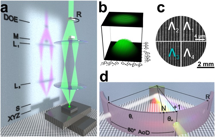
Figure 8.
Experimental methods. (a) Principle scheme of the symmetrical 4 f two laser beam interference ablation setup. From the top: a set of diffractive optical elements (“DOE”) on a rotational stage (“R”); a mask for blocking the zero and higher diffraction orders (“M”); two lenses (“L1”, “L2”); the sample (“S”); translation stages (“XYZ”). (b) Simulated interference fringes of two beams with Gaussian intensity distribution. (c) Schematics of a dot-matrix hologram with four different grating pitches (Λ1-4) used for validation of the rendering algorithm. Scanning electron microscope images of the actual gratings obtained under the same magnification are depicted in the respective quadrants. (d) Principle scheme of the setup used for spectral and spatial investigation of the diffracted light including the angle notation and experimental conditions used for spectral and image acquisition (“I” incident light, “R” specular reflection, “N” grating plane normal, “+1” first diffraction order, θi and θm are the angles of incidence and diffraction, “AoD” denotes the constant angle of detection).

