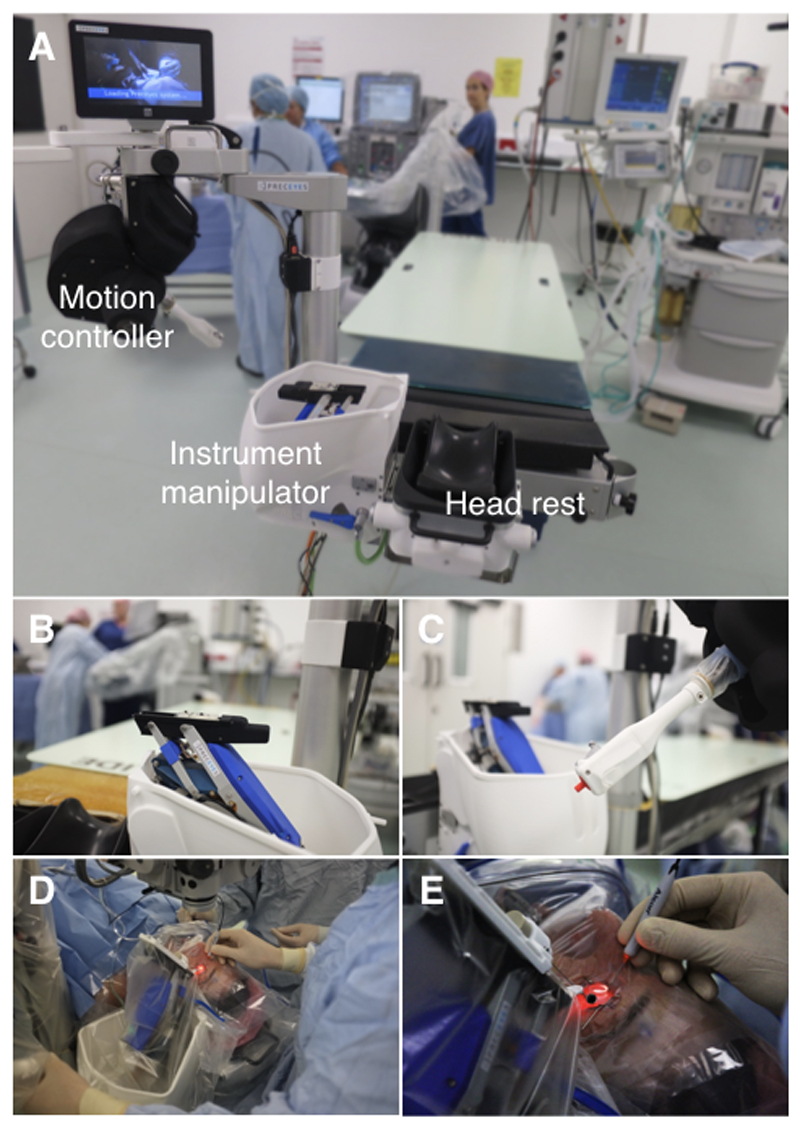
Figure 2. Robotic set-up.
(A) The robot system in position at the head of the operating table. Three main components of the robotic system include (B) an instrument manipulator mounted to the head rest, (C) a motion controller and (A) a table-mounted head rest. (D-E) The motion controller is manipulated in four axes (x, y, z and rotational) while the surgeon’s elbow and forearm is stabilised on the arm of the operating chair. With the clutch mechanism engaged – protruding grey switch in (C) – movements of the motion controller were mirrored by the instrument manipulator. (D) The sterile drape covered both instrument manipulator and motion controller. (D-E) The hybrid nature of the surgery allowed the surgeon to hold the endo-illumination (light-pipe) in one hand and to control the instrument manipulator loaded with a surgical instrument using the other hand. A separate electronics cabinet is placed outside the surgical area (see Figure 1).

