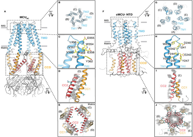
Figure 4. Comparison of cryo-EM structure MCUNC and NMR structure cMCU-ΔNTD.

(A and B) Side and top views showing the tetrameric configuration of MCUNC. (C) The selectivity filter sequence (yellow) of MCUNC is located at the beginning of TM2. (D) Close-up view of the hydrophobic interactions (silver spheres) between CC1 and CC2. Hydrophilic residues are colored in teal. (E) Viewed from the intermembrane space, CC1 (orange) and CC2 (red) of MCUNC form dimeric coiled coils within each protomer via extensive hydrophobic interactions (highlighted by silver spheres). (F and G) Side and top views showing cMCU-ΔNTD (PDB ID: 5ID3) forms a pentamer. (H) The “DΦΦE” motif (yellow) in cMCU is located at the loop connecting TM1 and TM2. (I) Close-up view of the hydrophobic residues (silver spheres) located on CC1 and CC2. Hydrophilic residues are colored in teal. (J) Viewed from the intermembrane space, CC2 (red) forms a pentameric helical bundle via hydrophobic interactions (silver spheres) pointing towards the central axis. Hydrophobic residues (silver spheres) on CC1 (orange) are exposed to the mitochondrial matrix.
