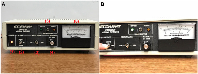
Figure 4. Shock generator and operation.

A. Shock generator: (1) POWER indicator (bulb is lit when power is on, power switch on back of shock generator); (2) OPERATE panel with toggle to select between “REMOTE” operation and “MANUAL” operation (manual operation is used for this test, toggle must be held down by experimenter); (3) METER RANGE panel with toggle to select between “LOW” and “HIGH” milliamp setting, corresponding to the top and bottom scales on the milliamps meter, respectively (must be set to “HIGH” for this protocol in order to achieve a setting of 2mA); (4) MANUAL panel with “SET SHOCK” knob that can be dialed to adjust shock setting; (5) SHOCK ROUTING panel with toggle to select between “SET/TEST”, used when manually setting the shock output during setting up, and “SUBJECT”, used when testing the probe for short circuits and when delivering shock to the subject while conducting the shock-probe defensive burying test; (6) milliamps meter, with the lower scale depicting the milliamps readout when the METER RANGE is set to “HIGH”; B. Setting the shock generator to deliver 2 mA. With SHOCK ROUTING toggle set to “SET/TEST” and METER RANGE toggle set to “HIGH”, experimenter holds down OPERATE toggle to “MANUAL” and dials “SET SHOCK” knob on MANUAL panel until needle on milliamps meter reads 2 mA, as depicted. The corresponding bulb on the SHOCK ROUTING panel will light up when OPERATE toggle is flipped to “MANUAL”.
