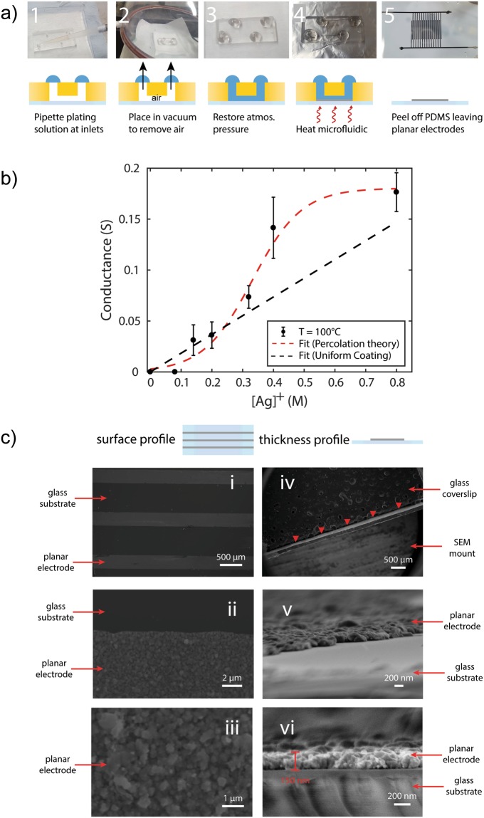
Figure 1.
Deposition and characterisation of electrodes. (a) Illustration of the plating process: 1, a PDMS mould is drilled with inlet holes and reversibly bonded to a glass coverslip or slide; 2, plating solution is pipetted so as to completely cover the inlets; 3, the microfluidic device is placed in a desiccator and allowed to degas for 5 minutes; 4, atmospheric pressure is restored allowing the plating solution to fill the vacuum in the main and side-channels; 5, the device is heated on a hotplate for 5 minutes at 100 °C; and 6, the PDMS mould is detached from the glass slide leaving planar electrodes. Shown are interdigitated electrodes (width = 300 μm, spacing = 200 μm). Scale bar corresponds to a length of 10 mm. (b) To determine the functionality of the electrodes, conductivity of main channel electrode is measured. Conductance varies as a function of the initial silver ion precursor concentration and shown are the results using electrodes cured at 100 °C. The dashed black line is an estimate of conductance when making the uniform coating assumption, which would apply in the case of non-porous films. The dashed red line is a Boltzmann fit to the data (R2 = 0.97) suggesting that electrode formation is in line with percolation theory. (c) SEM analysis of the planar electrodes produced on glass coverslips. i-iii: Images show the surface profile of the electrodes at increasing magnification. iv-vi: Images show the lateral profile of the electrodes to determine electrode thickness. The red arrow heads in iv indicate the location of the planar electrodes.

