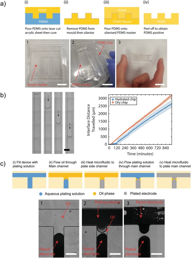
Figure 5.
Photolithography free methods of master production and electrode structuring using an immiscible phase. (a) A PDMS master (2) is created from a laser micromachined acrylic sheet (1) and used to produce PDMS channels to pattern microelectrodes (3). First, PDMS is poured onto a laser cut acrylic master 1/(i). A PDMS master is produced by (ii) removing the PDMS from the acrylic master and silanising it. (iii) The silanised PDMS serves as a PDMS master upon which more PMDS is poured. Finally, cured PDMS is peeled off the PDMS master 3/(iv) and used to produced microelectrodes. Scale bars are 20 mm. (b) On-chip evaporation is a known phenomenon whereby the solution filling the channel can diffuse into the PDMS over time due to its porosity. This results (left image, scale bar 300 μm) in the slow creeping over time of an oil-water interface along each ‘dead-end’ channel which forms the interdigitated electrodes. Graph shows results from images of the chip that were automatically acquired to measure the creeping rate of the interface for both an untreated (dry) chip and a chip that had been immersed in water for 24 hours (hydrated). (c) These were exploited to pattern microelectrode pairs with separation lengths much lower than that achievable by the channel geometry alone. Channels were (i) filled with plating solution by vacuum and (ii) the plating solution in the main channel was replaced with mineral oil then (1)/(iii) heat cured to form electrodes. 2/(iv) The oil in the main channel was replaced by fresh plating solution and remained separated from the plating solution in the channels by the immiscible oil phase and produced spatially separated electrodes (3)/(v). Scale bars are 300 μm.

