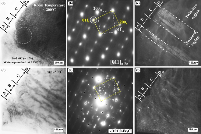
Figure 3.
TEM observation of the twinned structure in martensite plates after in situ heating: (a) bright-field image showing a twinned structure; (b) the SAED pattern obtained from the outlined region indicated by a dashed circle in (a,c) the corresponding dark-field image taken using the spot in (b,d) bright-field image of the same region as in (a) after the specimen was heated to 250 °C; (e) the SAED pattern from (d,f) the corresponding dark-field image of (d) obtained using the diffraction spot outlined by a dashed circle in (e). The calculated [101] zone axis diffraction spots of θ-Fe3C are superimposed on the experimental diffraction pattern in (e). The bright dots in (f) are carbide particles. The subscripts ‘m’ and ‘t’ denote matrix crystal and twin crystal, respectively.

