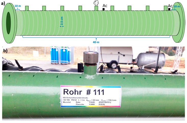
Figure 2.
(a) Schematic illustration of the employed fiber application approach relying on fiber helical wrapping around the pipe segments. Position of simulated leak and reference accelerometers “Ac” (only in pipe zone 2) is indicated as well; (b) Detail photo of one of the instrumented pipe segments showing a pipe side adapter and applied fiber.

