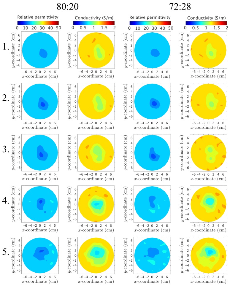
Figure 13.
Reconstructed images at of the inner chamber. Each row depicts a layer of the phantom, starting from Layer 1 (closest to the nipple) up to Layer 5 (closest to the chest wall). The columns correspond to (from left to right) the permittivity using the 80:20 mixture, the conductivity for 80:20, the permittivity for 72:28, and the conductivity for 72:28, respectively.

