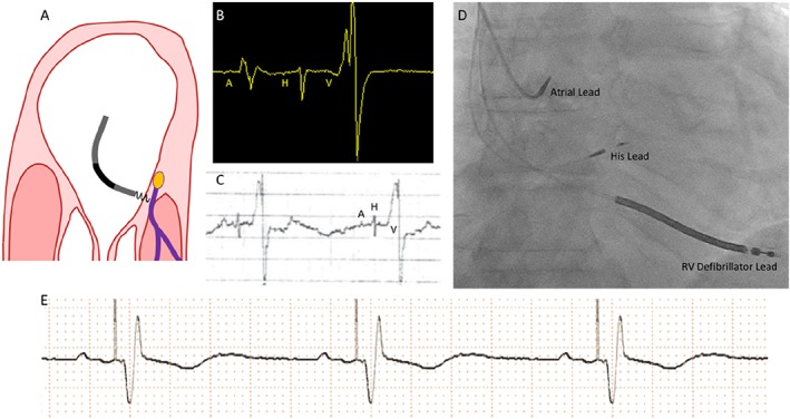
Figure 2.

(A) Intended area within right atrium for implantation of the His pacing lead. The target area is where the non‐branching part of the His bundle sits above the tricuspid valve on the right atrial—left ventricular part of the membranous septum. (B) Appearance of a single cardiac cycle recorded on an EP system, from a well‐positioned His lead. Note that the atrial component (A) is less than half the size of the ventricular component (V). There is a His signal (H) between the two. This appearance suggests a favourable location. (C) The electrogram can also be displayed using the Pace–Sense Analyser. It is advisable to measure initially a unipolar signal utilizing the atrial channel with a gain setting of 0.05 mV/mm and a sweep speed of 50–100 mm/s. The ventricular channel is not sufficiently sensitive to detect His potentials. (D) This anterior–posterior projection radiographic image shows the typical anatomical location for the His lead (labelled). (E) Rhythm strip showing successful His‐bundle pacing. RV, right ventricular.
