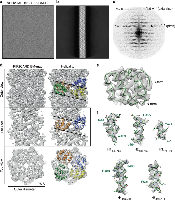
Fig. 6.
Cryo-EM structure of the RIP2CARD filament. a Cryo-EM image of NOD2CARDSs-RIP2CARD filaments used for structure determination. b, c 2D-class average (b) and corresponding power spectra (c) used for initial symmetry parameter estimation. d Final cryo-EM map of the three-dimensional RIP2CARD filament at 3.94 Å resolution (FSC in Supplementary Fig. 8c). Outer, inner and top view without (left) and with (right) RIP2CARD models fitted into one helical turn. e View of the RIP2CARD monomer fitted into the EM map showing only the main chain for clarity. f Zoomed-in views of the fitting of individual α-helices into the sharpened cryo-EM density. Helices are defined as in the sequence alignment (Supplementary Fig. 4) except for H1, which starts from I435 in the RIP2CARD monomer within the filament. Sidechains are shown as stick models. A few residues with clear EM density for sidechains are labelled

