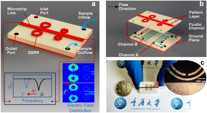
Figure 1.
Overview of the MIM sensor. (a) Mock-up view: a Rogers 4003c substrate is sandwiched between a top conductive signal layer and a bottom metallic ground plane. Chemical sample in the liquid phase enters the channels from the inlet port, shifting its resonant frequency from f0 to f ′ due to the change of electric field distribution. (b) Exploded views: the microfluidic flow-channel is formed inside the substrate by adopting craft-cutting technology and an adhesive. (c) A photograph of our metamaterial sensor taken with a background of Chongqing University logo to show its small dimension. Inset: local enlarged optical image of the resonator near the transmission line.

