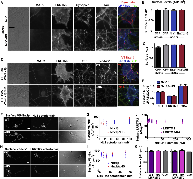
Figure S4.
Nrx HS Modification Is Required for the Function of NL and LRRTM2, Related to Figures 3 and 4
(A) Clustering of presynaptic marker synapsin induced by LRRTM2 in co-culture was abolished by Nrx knockdown and rescued by RNAi-resistant Nrx∗ but not Nrx∗ΔHS. All single channel images are shown here corresponding to the fields in Figure 3D.
(B and C) Surface levels of LRRTM2 (B) or NL2 (C) on the COS7 cells did not differ among Nrx knockdown and rescue groups; see Figure 3E for synapsin quantification. Neurons were transfected at plating with the rescue constructs, exposed to knockdown AAV vectors from DIV 3 and co-culture performed at DIV 13-14.
(D and E) HS modification of Nrx regulates its recruitment by NL1 or LRRTM2. Shown here (D) are all single channel images for LRRTM2 corresponding to the fields in Figure 3G; see Figure 3H for Nrx quantification. Surface levels of NL1, LRRTM2 or CD4 in the COS7 cells did not differ among groups in this assay for recruitment of V5-Nrx1β or the ΔHS mutant (E).
(F and G) Recombinant NL1 ectodomain bound more strongly to V5-Nrx1β compared to V5-Nrx1βΔHS expressed on the surface of neurons at 3 DIV (F); see Figure 3I for quantification. The level of surface expression of Nrx did not differ among all groups at the different concentrations of ligand (G).
(H and I) Recombinant LRRTM2 ectodomain bound more strongly to V5-Nrx1β compared to V5-Nrx1βΔHS expressed on the surface of neurons at 3 DIV (H); see Figure 3J for quantification. The level of surface expression of Nrx did not differ among all groups at the different concentrations of ligand (I).
(J) Surface expression of LRRTM2 in the Nrx LNS ectodomain binding experiment shown in Figure 4E did not differ between wild-type and the RA mutant at the different concentrations of ligands.
(K) Surface expression of LRRTM2 in the co-culture experiment shown in Figures 4F–4I did not differ between wild-type and the RA mutant. The left graph corresponds to the experiment in Figure 4G whereas the right graph corresponds to Figure 4I.
Error bars represent SEM. Scale bar: (A and D) 10 μm, (F and H) 20 μm.

