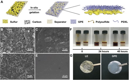
Fig. 3. Schematic diagram, SEM, and optical morphologies of the GPE applied in the Li-S battery.

(A) Schematic diagram of the in situ polymerization inside the battery system. Surface morphologies of (B) KB (Ketjen black)/S composite cathode and (C) separator before polymerization. Surface morphologies of (D) KB/S composite cathode and (E) separator after polymerization. (F) Permeation behavior of Li2S8 in LE (left) and GPE (right). Photo credit: Wen-Peng Wang, Institute of Chemistry, Chinese Academy of Sciences. (G) Optical photographs of separators harvested from the Li-S batteries with LE (left) and GPE (right) after 50 cycles at 0.5 C. Photo credit: Feng-Quan Liu, Beijing Normal University.
