
Figure 8.
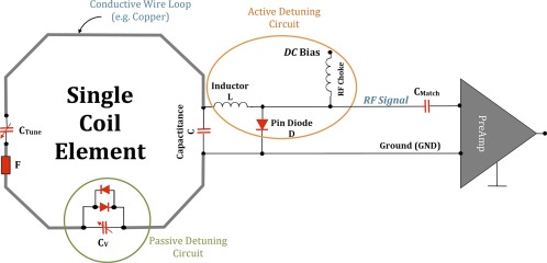
A typical circuit schematic for a receive‐only coil element. In this case, the loop comprises a conductive wire with two tuning capacitors (CTune and C) to fine‐tune the coil frequency, a detuning trap (L and pin diode D) to actively deactivate/detune (turn off) the loop while RF excitation by the transmit coil, and a matching capacitor (CMatch) to transform the element impedance to 50 Ω of the preamplifier, which finally amplifies the MR signal. The pin diode D is powered by a certain DC bias. The passive detuning circuit, consisting of an adjustable capacitor CV and crossed diodes and serves, like the RF fuse F, as a second stage of safety to the Rx loop during transmission by the Tx coil, and as well for the patient. This example coil thus has three redundant safety features to prevent interactions between the Tx coil and the receive loop that could cause heating or other safety concerns.