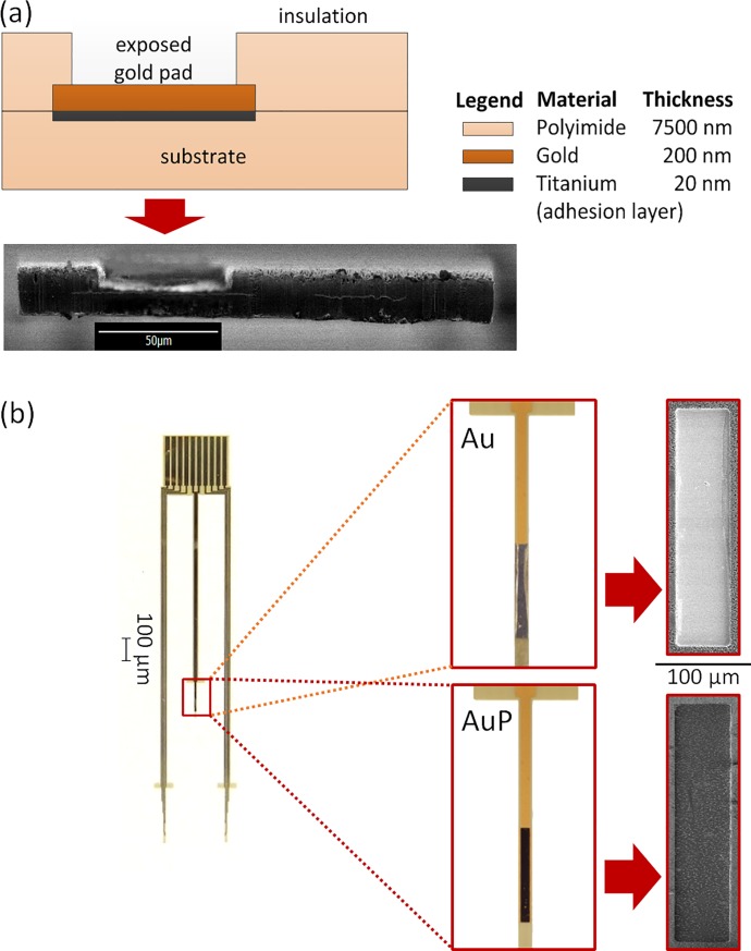
Fig 3. Micro fabricated gold electrodes.
(a) Cross-sectional illustration (top) and SEM image (bottom) of a microfabricated gold electrode. The two thin horizontal lines running along the SEM image are the gold layers. (b) Microfabricated electrodes used in the experiments (left). The flat top end is inserted to an FFC connector for for connection to external circuit. (inset) Optical microscope and SEM images show an electrode pad at the electrode tip before and after electropolymerization using PEDOT:PSS conductive polymer.

