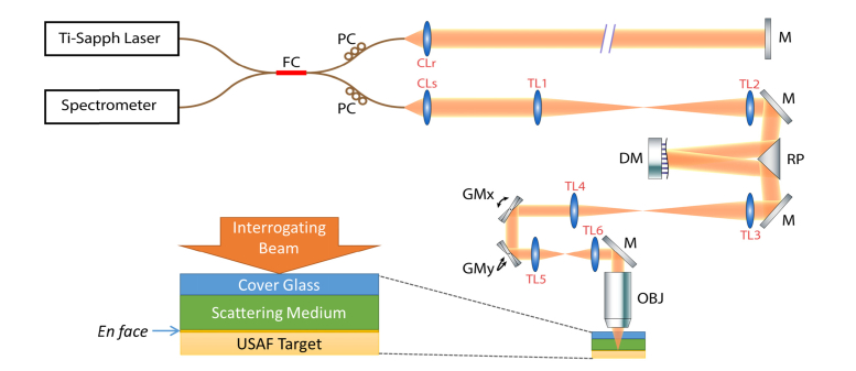
Fig. 2.
System diagram for AD-OCT setup and sample configuration. FC: 50-50 Fiber Coupler, PC: Polarization Controller, M: Mirror, DM: Deformable Mirror, RP: Right-angle Prism, GMx and GMy: Galvanometer mirror along x and y directions, OBJ: Objective Lens, CLr: Reference arm collimating lens, CLs: Sample arm collimating lens (f = 50 mm), TL1 and TL2: Telescope lens 1 and 2 (f1 = f2 = 400 mm), TL3 and TL4: Telescope lens 3 and 4 (f3 = 400 mm, f4 = 250 mm), TL5 and TL6: Telescope lens 5 and 6 (f5 = f6 = 100 mm). All the telescope lenses are AR-coated achromatic doublets. Folding mirrors in the system are not shown.

