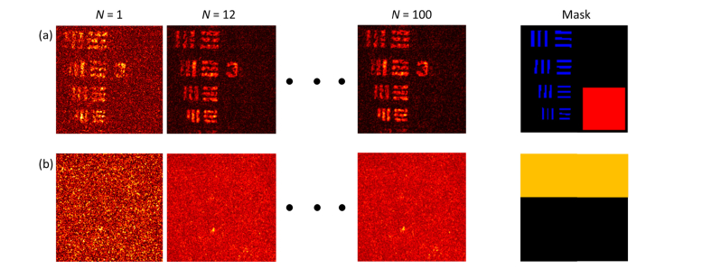
Fig. 7.
Images and masks used for the SBR and speckle contrast calculations. (a) Examples of USAF target en face view, and the SBR mask used to define the areas of expected signal and background. Any voxel within the blue regions are defined to be the signal, while the red region is defined to be the background. (b) Examples of en face view inside the scattering layer, and the speckle mask used to define the area of interest. Any voxel within the yellow region is considered as the speckle.

