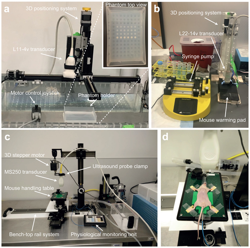
Figure 4. Ultrasound setup for in vitro and in vivo imaging.
(a) Setup of the in vitro imaging system with the Verasonics L11–4v transducer mounted on a 3-D translatable clamp (computer-controlled) and a fixed imaging phantom holder. Inset shows an agarose phantom loaded with GV and polystyrene samples prior to imaging. (b) In vivo imaging setup with the Verasonics L22–14v transducer, mounted on a 3-D positioning system (manual), an animal mounting platform with a heating pad and a syringe pump for controlled sample injections. (c) Setup of the Vevo imaging station includes the ultrasound probe clamp attached to the 3D stepper, the mouse handling table and the physiological monitoring unit. All components except the physiological monitoring unit are attached to the bench-top rail system. (d) Animal positioning with the mouse being laid down in a supine position with the nose and mouth in the nose cone and each paw extending outwards onto the electrodes and secured with surgical tape. A rectal probe is used to monitor the core temperature of the animal.

