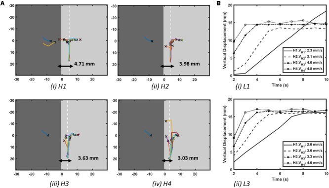
FIGURE 3.

Effect of AWT gradients on the drift velocity of RD in atrial slab (Study 1a) with aFK model. (A) Trajectories of the core of RDs initiated at multiple locations on the slabs with varying step height (H1-4, see Figure 2D). Here, the X marks the site of the initial RD core for every location and the white dashed line in each slab indicates the location where the core of all the RDs stabilized after anchoring to the AWT step. (B) Vertical displacements of the RD core for locations L1 on the thick side and L3 on the thin side of the step (shown in Figure 2D) over 10 s are shown in panel (Bi,ii), respectively, for each of the slabs with height H1-4. As the height of the step was increased, velocity of the vertical drift of the RDs also increased.
