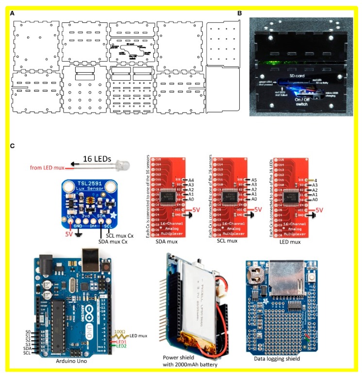
Figure 3.
Arduino Uno (marked in the blue square in figure C) used in the work of Pardee, et al. published in Cell 2016 [23]. (A) Line drawings used to cut the housing for the electronic reader from black acrylic using a laser cutter. (B) Image of the 16-reaction reader from the front. Chip containing paper-based sensors slides into the slot illuminated by the green light. Reader dimensions: 106 mm wide × 116 mm deep × 96 mm high. (C) Components and circuit design used to assemble the electronic optical reader. Reproduced with permission from [23].

