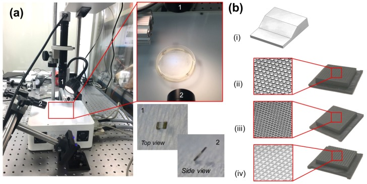
Figure 6.
(a) The MFG-100 system with the top camera (1) and side camera (2). The paper surface inside a Petri dish at the center of the workspace. Top and side views of a TUM as seen through the cameras. (b) Qualitative diagram of the various terrain geometries designed and fabricated: (i) inclined plane, (ii) cylindrical bumps, (iii) honeycomb and (iv) knurled.

