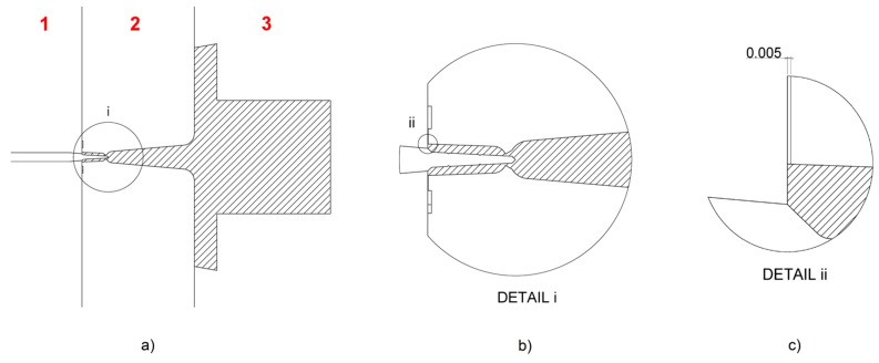
Figure 3.
Mould design. (a) Mould cross-section showing the part and feed system location (hatched) with respect to the three mould plates (numbered in red). (b) Detail of the moulded component and ring gate. (c) Detail of the venting channel machined on the insert at the end of the flow path (nominal thickness in mm).

