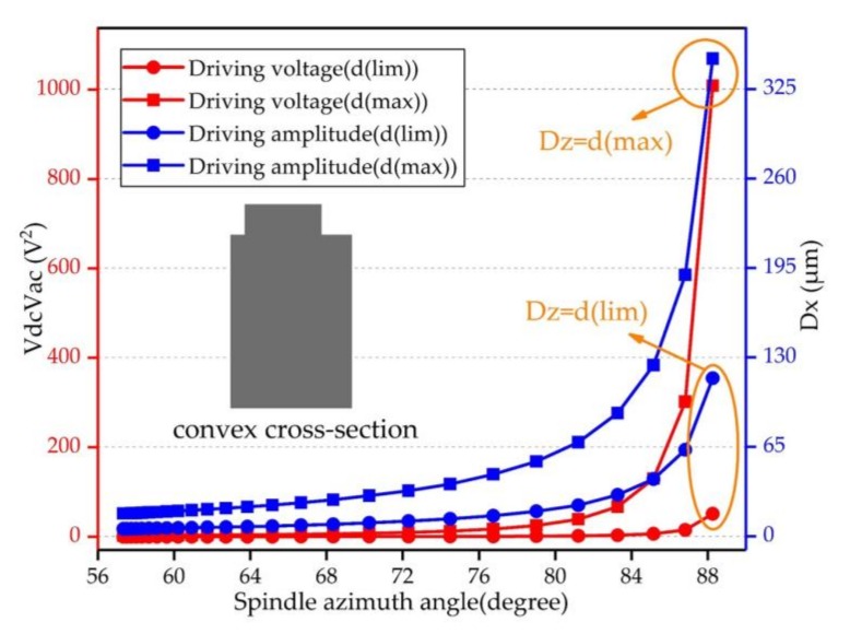
Figure 5.
Driving voltage and driving amplitude of the convex cross-section beam—this figure has two Y axes. The ultimate in-plane displacement of the driving mode is fixed, the spindle azimuth is changing. The left axis shows the voltage required to achieve the ultimate in-plane displacement of the driving mode under different spindle azimuth angles. The right axis shows the corresponding ultimate driving amplitude of the gyroscope.

