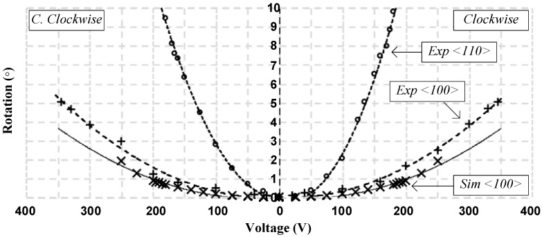
Figure 9.
Platform angular displacement for left and right actuation of the third design with fitting curves showing more than ±5° both sides for <100> anchor orientation and ±9.5° for <110> anchor orientation where the “×” data points represent simulated data, the solid line is a fit to the simulated data, the “+” data points represent experimental measurements on the <100> fabrication plane, the “o” data points represent experimental measurements on the <110> fabrication plane, and the dotted lines are a fit to the experimental measurements.

