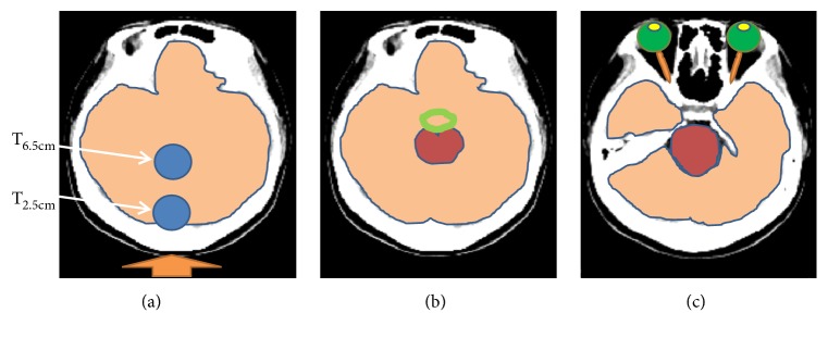
Figure 2.
Overview of the simulated head models established for dose calculations at two different tumor depths. Panels (a–c) represent the structures affected by BNCT at tumor depths of 2.5 cm and 6.5 cm. In panel (a), beam direction is indicated with an orange arrow pointing toward the posterior scalp, the blue circles represent the positions of the virtual tumors, and brain tissue is shown in light orange. In panel (b), the circle of Willis is represented as a green circle and the brainstem is shown in dark red. In panel (c), the lenses are shown in yellow, the eyes are shown in green, and the optic nerve is represented by orange lines.

