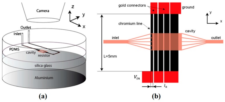
Figure 37.
(a) Overview of the experimental device by Selva et al. (b) Top view of their experimental setup. The liquid fills the cavity positioned above the chromium resistors which have been placed in series and are connected by gold wires. Reproduced with permission from [200], B. Selva, J. Marchalot, and M.-C. Jullien, “An optimized resistor pattern for temperature gradient control in microfluidics”, Journal of Micromechanics and Microengineering, vol. 19, p. 065002, 2009. Copyright 2009, IOP Publishing, all rights reserved.

