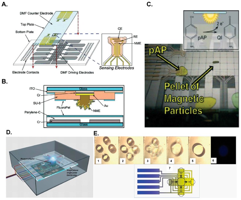
Figure 6.
DMF further integrated another platform to perform immunoassays as described in: (A–C) Rackus et al. [36]; (D,E) Zeng et al. [62]. (A) DMF device with integrated nanostructured microelectrodes; (B) Schematic of a cross section of a DMF device; (C) Electrochemical measurements of the DMF device; (D) Schematic of the DMF chemiluminescent detector; (E) Mixing process on the DMF device (1–5); chemiluminescent photo (6) and schematic diagram (7). Reproduction of the figures is made with permission of Royal Society of Chemistry.

