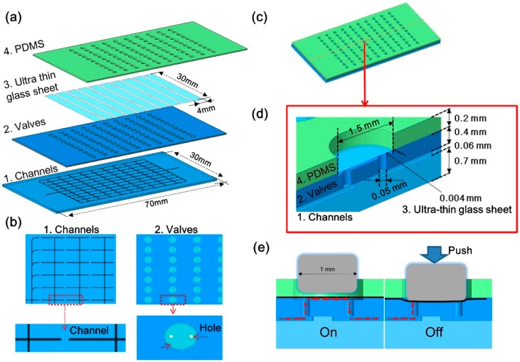
Figure 2.
Schematic illustrations of fundamental design and principle of large-scale integrated microfluidic device with all-glass valves. (a) Schematic illustration of the layer structure of the device; (b) Details of layer 1 and layer 2; (c) Four-layer-bonded image of the device; (d) Cut-away and assembled illustrations of a single all-glass valve. The ultra-thin glass sheet seals the chambers on the valve layer, and the chamber gap is 50 μm when the valve is open. (e) On: Initial state of the valve. Off: Applying pressure to the ultra-thin glass sheet pulls the sheet to the valve layer and closes the valve.

