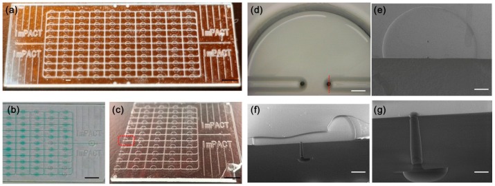
Figure 4.
Photographs and valve profile images of prototype. (a) Photograph of a large-scale integrated microfluidic device with 110 all-glass monolithic membrane valves; (b) Image of valves with colored medium loaded; (c) Image of chip after the ultra-thin glass sheets were bonded and cut in half for observation. The black scale bar is 5 mm; (d) Image of single valve unit from top side. The white scale bar is 0.2 mm; (e) SEM image of valve unit before ultra-thin glass sheet bonding; (f) Cross-sectional view showing the details of the valve after glass sheet bonding. The white scale bar is 0.2 mm. The location of the cross-sectional view is shown in (d) with the red dotted line; (g) Enlarged cross-sectional view of single through-hole structure. The white scale bar is 0.05 mm.

