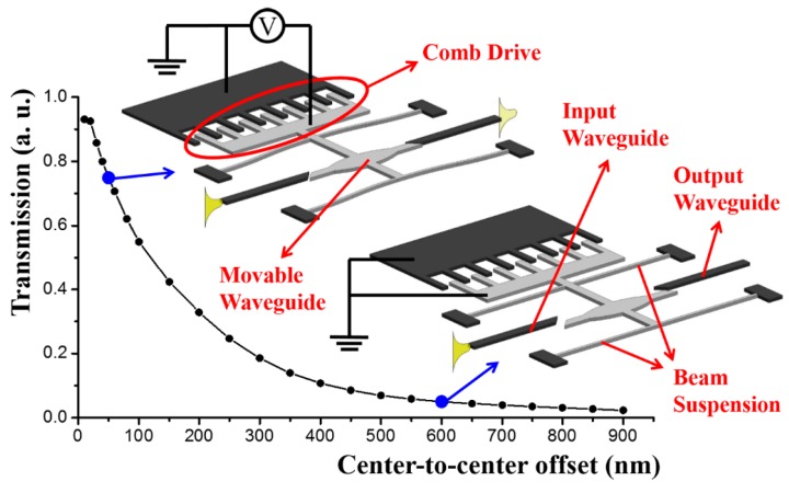
Figure 2.
Finite difference time domain (FDTD) simulation results of the normalized transmission of the segmented waveguides configuration with respect to the center-to-center offset of the waveguide segments. The inserts denote the “on” and “off” states of the switch. The light grey parts denote movable structures while the dark grey parts indicate fixed structures. (The schematics in the figures below follow the same rule.)

