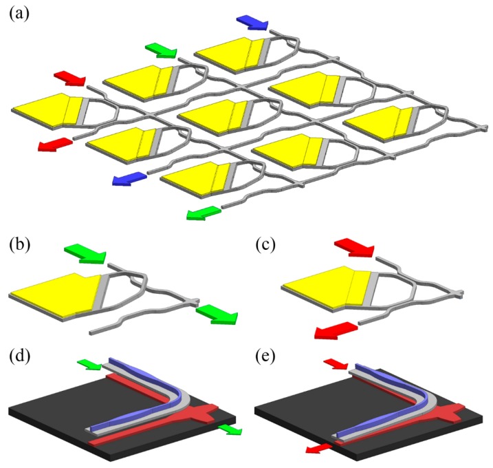
Figure 4.
(a) Schematic of a large scale switch based on variable coupled waveguides. The yellow structures denote deposited gold layers. (b,c) Illustration of the through and drop states of a unit cell. (d,e) Illustration of the through and drop states of a unit cell of an improved design, in which the blue and red structures denote the suspended rib waveguide and the fixed rib waveguide, respectively.

