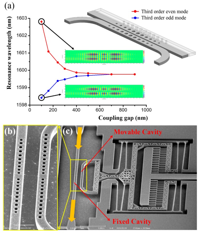
Figure 10.
(a) FDTD simulation result of the third order even and odd modes indicating the wavelength shift of dual-coupled nanobeam cavities with respect to coupling gap variation. The mode profiles (when coupling gap is 100 nm) are inserted. (b,c) SEM images of (b) close-up view of the dual-coupled nanobeam cavities and (c) NEMS comb drive controlled dual-coupled nanobeam cavities system.

