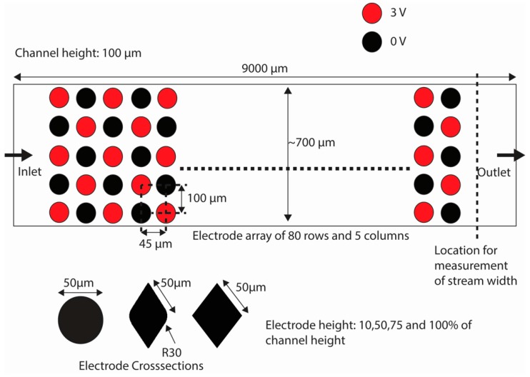
Figure 3.
The top view of the model used for numerical analysis with the dimensions and electrode polarity is shown in the figure. The electrodes are arranged in a manner that they lie in straight rows and symmetrical rows. However, the electrodes are polarized alternately using either 3 or 0 V. The three cross-sections studied in this work are shown: circles, lens and diamonds. The model shown is not true to the scale, but represents the actual shape of the electrodes and channel.

