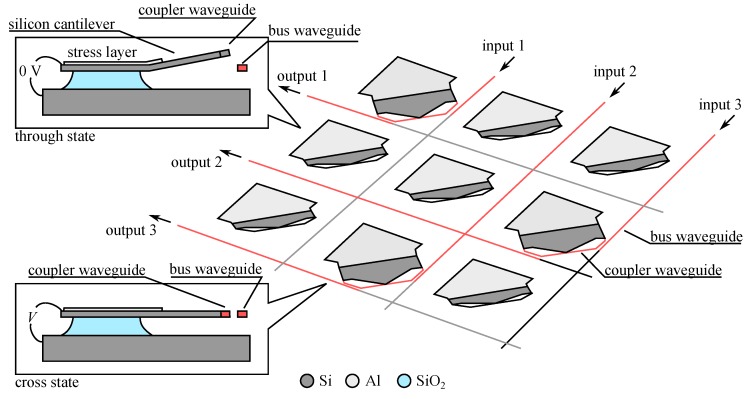
Figure 22.
Principle of operation of 3 × 3 non-blocking optical switch matrix using movable evanescent coupler on a bending actuator (adapted from [29]) (inset top: cross-section of the switch cell in the through state showing the bending due to the stressed metal layer) (inset bottom: cross-section of the switch cell in the cross state after applying a voltage V).

