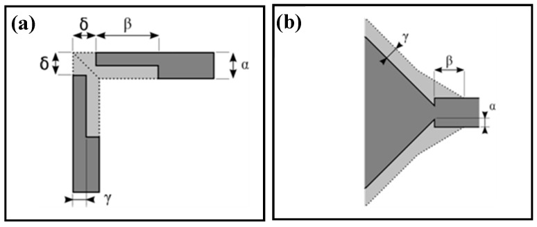
Figure 6.
Layout of the compensation structures and definition of parameters: (a) layout Q for intersection of perpendicular channels; (b) layout I for intersection of channel with cavity. Dotted line and gray area shows the projected etch profile. The dark gray area is the open area of the etching mask.

