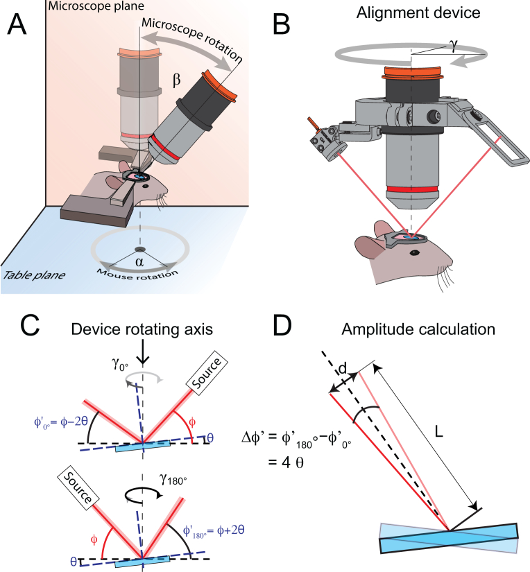
Fig. 2.
Tilt angle measurement principle. (A) In our configuration, the microscope frontend can be rotated along the microscope plane (in orange) by an angle β and the mouse around the table plane (in blue) by an angle α. (B) The tilt angle can be estimated by mounting the device on an objective. The device comprises a laser source and a target screen placed on opposite sides of the rotating ring. (C) If a tilt θ is present, the reflection angle of the laser beam (red line) will vary depending on the orientation of the device around the optical axis (dotted line), as shown in this panel. (D) This variation in reflective angle ϕ′ will entail a change in position on the target d, depending on the tilt angle θ and the distance L between the cover glass window (blue) and the target.

