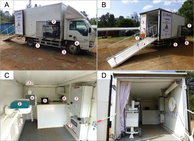
Figure 2.
Mobile diagnostic unit equipment placement and descriptions. (A) Anterior side view: (1) fuel can; (2) slide-out electrical generator; (3) grounding chain; (4) grounding rod (hammered into the ground at each site). (B) Posterior side view: (1) standing platform for radiologists; (2) power factor correction device; (3) shielded door for radiologists to stand behind; (4) patient access ramp; (5) onboard generator fuel can; (6) redundant grounding devices (installed at each site); (7) slide-out electrical generator. (C) (interior view, detailed): (1) fold-down bed for supine radiographs; (2) X-ray generator; (3) negative pressure ventilation; (4) digital radiography cassette; (5) radiography laptop computer; (6) onboard 230 V power and charging; (7) power control, safety and distribution systems. (D) Interior view, general layout, shown with shielding door open.

