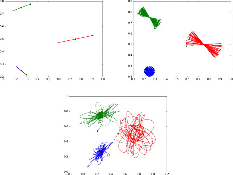
Figure 4.
Showing landmark flowing with potential energy giving inputs that enters continuously along the path of the flow ṗ + g = −(dυ)T ◦ φp. Potential energy term U giving the g terms expressed by the distance squared between the green landmark and the target red landmark. Panel 1 is for a small kernel (0.01); panel 2 is for a larger kernel .05, notice the trajectory slowly rotates, panel 3 shows large chaotic motions for kernel 0.1. See text in “Forces associated to Internal Potential Energy” section for more detail.

