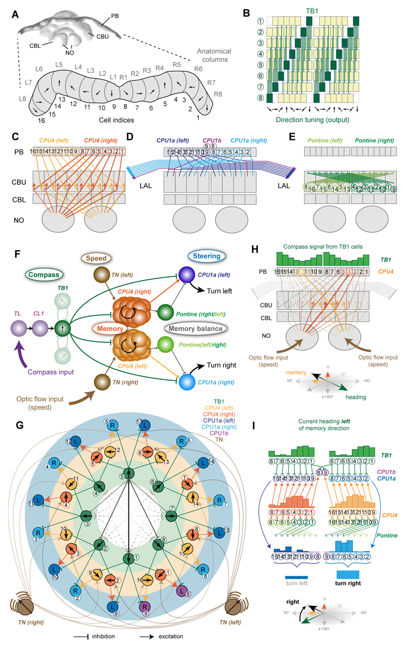
Figure 5. Deduction of circuit-model from anatomically plausible connections in the central complex.
(A) 3D reconstruction of the Megalopta genalis central complex (CX); posterior view. Enlargement: Schematic protocerebral bridge (PB) with columnar organization highlighted. Proposed head-direction tuning of direction cells indicated for each column (based on data from flies [8]. (B) Projection pattern of TB1-neurons in the PB; direction tuning indicated as arrows; green columns: output fibers; yellow columns: input fibers. (C-E) Schematic interhemispheric projection patterns of CPU4-neurons (C), CPU1-neurons (D), and pontine neurons (E). (F) Principal connections of all cell-types included in the proposed path integration circuit. Shown are all connections of one TB1 direction cell irrespective of columnar identity of individual cells (only two out of six connections to other TB1-cells are shown). (G) Ring-like topology of proposed path integration circuit, obtained using a force-directed graph. Neurons are arranged in three layers: Direction cells (TB1), memory cells (CPU4), and steering cells (CPU1), with connections matching the interhemispheric projection patterns in B-E. Only one CPU4 cell per column is drawn (representing the entire columnar population). Connections between TB1-neurons form a ring attractor network (solid lines: connections of one cell; dashed lines: remaining cells; line thickness: connection strength). CPU1-neurons receive inputs from CPU4-neurons with a rightwards (yellow) or leftwards (orange) shift relative to their TB1-input. Arrows: directional tuning (TB-neurons), integrated direction preference (CPU4-cells). Pontine neurons were omitted for clarity. (H) Illustration for memory acquisition during outbound journey. Width of lines indicates activation strength. Memory accumulates opposite to outbound heading direction and is encoded as two partial vectors (each generated by the CPU4-cell population on one brain hemisphere). (I) Illustration of how memory is combined with current heading to generate an imbalance between the right and left CPU1-neuron population activity. The activity in each cell is indicated by the height of the bars above the cell-indices. Current heading: green arrow (bottom); target direction encoded by memory (black arrow). Activity of TB1 (inhibitory) and CPU4-cells (excitatory) are compared by CPU1-cells. Due to the one-column shift between CPU1 and CPU4 projections, this results an imbalance in the combined CPU1 output that initiates turning towards the target. Pontine neurons have the identical activity as CPU4 cells (not shown) and normalize the memory output from each CPU4 population by subtractive inhibition of neurons with opposite directional tunings. For a more mathematical explanation of how the steering signal in generated see Figure S6B-D. Abbreviations see Figure 1. See also Figure S4,S5,S6.

