
Figure 6. Bifurcation plots for the EGF-TGFβ3 circuit implemented in the virtual palate model.
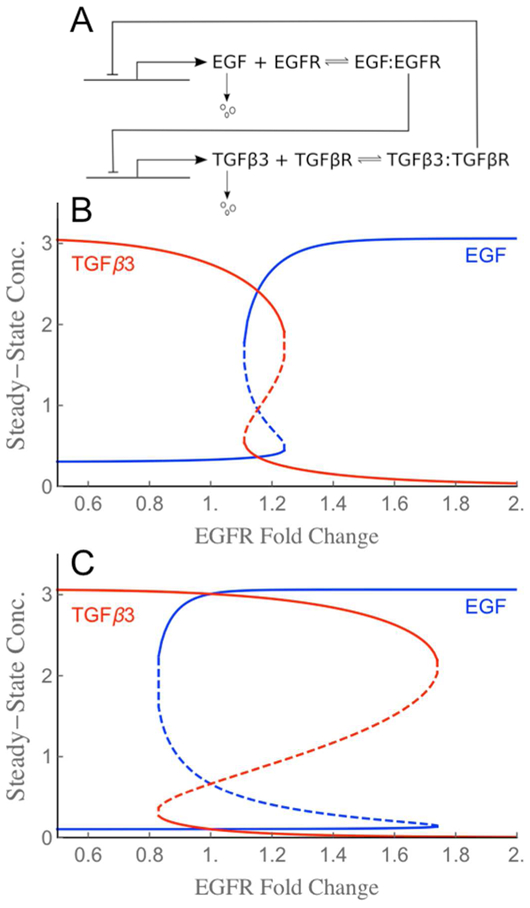
(A) Schematic of the mutual inhibitory circuit. Symmetry between EGF and TGFβ3, as well as the structure of the bistable zone can be broken through parameter choices. (B) Steady-state behavior for base receptor levels that yield a narrowly bistable switch with low hysteresis. For any EGFR fold-change in the bistable zone from 1.1 to 1.3, the circuit has three steady state solutions (i.e., three solutions for EGF and three for TGFβ3): two of the solutions are stable (solid lines) and one unstable (dashed line). (C) Increasing and equating the base receptor levels yields a switch with a wider bistable zone (0.8 to 1.8) and higher hysteresis (unstable solutions dashed).