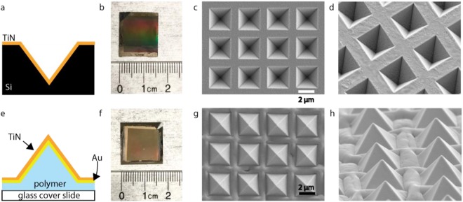
Figure 2.
Inverted and upright TiN micropyramids. (a) A schematic of the cross section of the inverted pyramid design. (b) The inverted pyramid substrate next to a ruler. (c) Top-down view of the inverted pyramids with SEM. (d) Tilted SEM of the inverted pyramids, showing consistent fabrication dimensions for each structure. (e) A schematic of the cross section of the upright pyramid design. (f) The upright pyramid substrate next to a ruler. (g) Top-down view of the upright pyramid design taken via SEM. (h) Tilted view of the inverted pyramid design taken via SEM. This shows a consistent rising of the film in between each pyramid.

