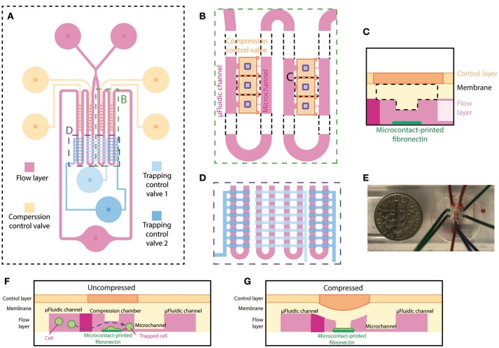
Figure 1.
Overview and design of the microfluidic device for single-cell compression. (A) The top view of overall design of the device. The flow layer is labeled in magenta, and the control layer consists of trapping control valves (blue) and compression control valve (orange). (B) The zoomed-in top view of the compression chamber (marked in A) and the meandering microfluidic channel in the device. The orange compression control valve is on top of the compression chamber in the flow layer. The purple rectangles are the designed block attached to the deflection membrane for compression. (C) Side view schematic of the compression chamber. A rectangular block and fibronectin island are unique features of this device. (D) The zoomed-in top view of the main meandering microfluidic channel (marked in A) and trapping control valve (blue). The inside two columns and outside two columns are controlled separately by two different trapping control valves. (E) A picture of the device. (F,G) Side view schematics of the device when the compression control valve is uncompressed (F) or compressed (G) on a cell spread on the fibronectin island.

