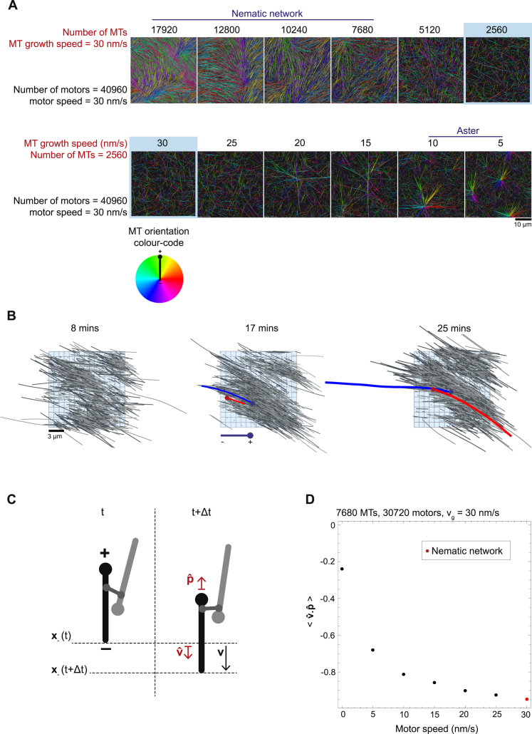
Figure S4.
The Nematic Network State Exhibits Extensile Behavior, Related to Figure 4
There is a gradual transition between the nematic and aster state upon decreasing microtubule number and microtubule growth speed. (A) Snapshots of final simulation outcomes as parameters are systematically varied. The number of microtubules (top) and the microtubule growth speed (bottom) are varied while holding all other parameters constant. The colored blue border indicates simulations with the same parameter values. The type of organizational state is labeled above the simulation snapshot. All simulation images are three-dimensional projections of a snapshot onto the x-y plane. Colors indicate microtubule orientation. Color code: below, left. For visual clarity unconnected microtubules bearing no crosslinking motors are displayed in gray. See Table S1 for simulation parameters if not shown. (B) Time-course showing simulation snapshots of a nematic network (taken from Video S4). An aligned domain of microtubules is isolated from the network and shown alone so that the extension of the domain can be clearly seen. Microtubules within this domain are selected on the basis that any point along their length falls within the volume described by (−5 < x < 10 μm, −10 < y < 5 μm, −0.2 < z < 0.2 μm) (shown by a colored blue box, the origin is located at the center of the simulation space) and their long axis is oriented at an angle of −93° < θ < −53° with respect to the vertical. Microtubules colored in light and dark gray point in opposite directions. The trajectories of two oppositely oriented microtubules are highlighted (blue and red). The distance between their static minus ends increases due to anti-parallel sliding by motors while their plus-ends grow. Overall anti-parallel sliding results in the narrowing and lengthening of the entire domain along its long axis over time. (C) Schematic illustration of the calculation of the parameter (STAR Methods) for a single microtubule (black) driven backward via a crosslinking motor connecting it to an anti-parallel microtubule (gray). (D) A plot showing the average value (STAR Methods) for a range of different motor speeds. Each point represents one simulation and the final point (red) represents the nematic network state. The increasing negative value of with motor speed demonstrates that microtubules are being continuously transported backward by motors, which drives the extension of the aligned microtubule domains.

