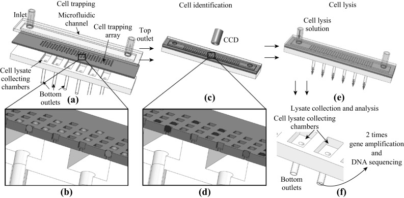
Fig. 1.

The schematic view of microfluidic chip and its operation. a The cell mixture is pumped into a microfluidic chip which consists of three layers: the microfluidic channel, the cell trapping array and the cell lysate collecting chamber. The flow velocity was 3 μL min−1. b Cells are trapped in microwells. The square microwell is designed to fit only one cell. c The chip was fluorescently examined to identify cells with specific protein expression. d Blue balls represent negative cells which exhibit only blue color of DAPI, while green balls represent positive cells which exhibit both green color of FITC and blue color of DAPI. e The cells in microwells are lysed by inputting cell lysis solution through the microfluidic channel. The cell lysate is directed to cell lysate collecting chambers. f The cell lysates are separately collected from cell lysate collecting chambers for the following DNA amplification and sequencing. To clearly demonstrate the chip structure, the schematic figures do not follow the exact well number and dimension
