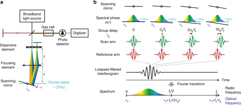
Fig. 1.
Schematic and conceptual illustration of phase-controlled Fourier-transform spectrometer. a Schematic of the system. The system consists of a broadband light source, a scanning Michelson interferometer with the rapid-scan phase-controlled delay line, a sample gas cell, a photodetector, and a digitizer. The delay line consists of a dispersive element, a focusing element, and a scanning mirror aligned in a reflective 4f-configulation. The broadband light is focused at the Fourier plane in the 4f system after spectral separation by the dispersive element such that each spectral component is mapped on a different position at the Fourier plane. The scanning mirror changes its angle at an angular frequency of ω and reflects the light with angled directions. The beam traveling through the 4f system is retro-reflected with an end mirror and goes back along the same path. The corresponding optical frequency of the pivot position of the scanning mirror in the Fourier plane is indicated as ν0. b Concept of PC-FTS. The upper part shows how the interferogram is obtained in the time domain. For simplicity, the light fields are depicted as a pulse train with zero carrier-envelope-phase as shown in the pulses in the reference arm. Here, fs denotes the sampling rate, which may be determined by the pulse repetition rate or sampling rate of the digitizer. At each time frame, the light field in the scan arm acquires a linear spectral phase that is proportional to the angle of the scanning mirror in the delay line. The linear spectral phase ramp adds a group delay and phase delay to the light field. The pivot frequency ν0 is converted to the zero frequency in the down-converted RF spectrum after Fourier-transformation. Therefore, the down-converted spectrum can be positioned inside of the Nyquist range (0−fs/2) by adjusting ν0

